Charging stations for electric cars – diagnostics and safety measurements
The rapid increase in the number of electric vehicles on our roads has necessitated an equally rapid development of their charging infrastructure. This is just the beginning of the development path for a new segment that is set to replace the hitherto powerful internal combustion vehicle sector in most countries around the world.
Regardless of the technology used, safety has always been a key issue in road transport. For electric vehicle use, in addition to road safety itself, there are also factors relating to the appropriate use of the electricity required to drive them. The process of charging an EV vehicle is the path from the generation of energy at a power plant or from RES through its transmission and distribution to the EVSE charging points. Only from there does the charging of the batteries in the vehicle take place. Safety should be ensured at each of these stages of the process. One element of its guarantee is the electrical tests and measurements carried out during commissioning as well as those carried out periodically in accordance with current electrical standards.
Charging stations can be installed in a variety of locations such as petrol stations, car parks, underground garages, or simply next to single-family homes. Generally speaking, they can be divided into AC and DC type stations. AC stations tend to be of lower power, in the 3.7 kW – 22 kW range. DC charging stations, often referred to as fast charging stations, can already charge at up to 350 kW. They will therefore vary according to needs and connection conditions, which unfortunately are often a major constraint. However, regardless of the station for which the connection is prepared, appropriate electrical measurements should already be taken at this stage. This is because the connection itself also determines the safety of the user and the devices connected to it.
The type of measurements at the charging stations themselves will vary somewhat due to their mode of operation and construction. We will mainly focus on AC stations, although many of these measurements will also be suitable for DC stations.

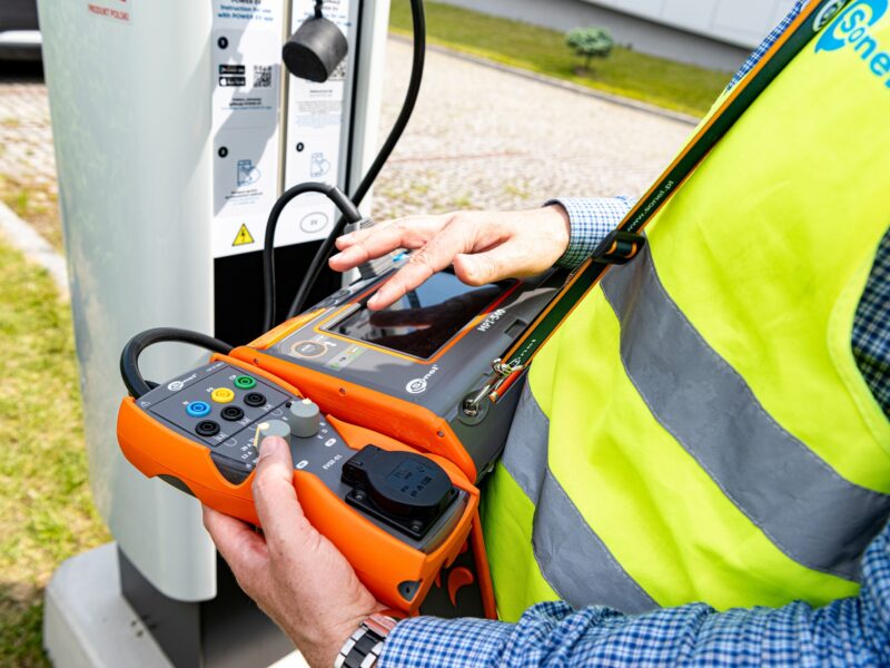
Photo 1. Safety measurements of vehicle charging stations
Standards and legal acts
The basis for properly performed examinations and tests should be based on the applicable standards and legal acts. They are a guarantee of the application of proven and up-to-date technical knowledge in a particular area, in our case in the area of electromobility and electrical installations. The main standards we can currently rely on are:
- EN 61851 – Electric vehicle conductive charging systems
- HD 60364 – Low voltage electrical installations
In particular:
- Part 6: Checking
- Part 4- 41: Protection for safety – Protection against electric shock
- Part 7- 722: Requirements for special installations or locations – Supplies for electric vehicles
A great complement to these are the following standards:
- EN 62196 – Plugs, socket-outlets, vehicle connectors and vehicle inlets – Conductive charging of electric vehicles
- EN 62752 – In-cable control and protection device for mode 2 charging of electric road vehicles (IC-CPD)
- EN 50620 – Electric cables – Charging cables for electric vehicles
- IEC 62955 – Residual direct current detecting device (RDC-DD) to be used for mode 3 charging of electric vehicles
- EN ISO 15118 – Road vehicles – Vehicle to grid communication interface
Measurements at electric vehicle charging stations
The most important measurements and checks to be carried out at an electric vehicle charging station therefore include the following:
Inspection
These are not measurements yet, but a set of activities and things to check that we should do before the attempts. These include, inter alia, the verification of:
- protection measures against electric shock;
- fire protection measures;
- selection of conductors with regard to current-carrying capacity and voltage drop;
- selection and adjustment of safety and signalling devices;
- correct designation of neutral and protective conductors;
- presence of diagrams, warning notices or other similar information;
- designation of circuits, overcurrent protection devices, switches, terminals, etc;
- correctness of the cable connections;
- presence and continuity of protective conductors,
- accessibility of devices, enabling convenient operation, identification and maintenance
- condition and completeness of the station housing
Measurement of resistance of protective and equalising conductors (continuity)
To ensure correct electric shock protection, and the safety of users and devices, the correctness of the protective connections to accessible conductive parts and their correct earthing must be checked. This is one of the most important tests. In practice, we measure the resistance between the PE bar and the individual accessible conductive parts of the station.
Earthing measurement
Resistance measurements of the working earthing should be taken if they are used. The quality of earthing has a direct impact on the safe use of the device and, above all, on the effectiveness of electric shock and lightning protection. The measured resistance allows us to determine the value of the contact voltage that can arise between the various conductive parts on the protective conductor. Nowadays, manufacturers of measuring equipment offer the possibility to measure by various methods, but the technical method is still the most popular. In the case of typically “urban” conditions and the impossibility of driving measuring probes into the ground, we can use clamp methods.
Insulation resistance measurement
By insulating the active parts of the circuit, basic protection against direct contact is implemented. This not only prevents the user of the installation from being electrocuted if a conductive part is touched, but also protects the installation itself from a short circuit between conductors or between a phase and the housing of a device connected to the power grid. In the case of charging stations, it is important to remember that when measuring the insulation resistance on the charging cable side, we are only measuring a short section – to the “inside of the station”.
It is important to be aware of the fact that, depending on the construction and components used, the application of voltage to the station’s circuits can, in extreme cases, result in damage or activate the protection devices. It is therefore necessary to have adequate technical knowledge and familiarity with the object examined. We should, of course, also examine the cables supplying the charging point itself. According to the standards, the rated voltage of the station determines the test voltage.
Short circuit loop impedance measurement
One element of protection against indirect contact is the use of overcurrent protection in electrical circuits. A sufficiently low value of the short-circuit loop impedance is a prerequisite for their correct operation within the time required by the standard. This value in turn directly affects the expected short circuit current. We must therefore relate the result of the measurement to the protections applied to the circuit. Quite a few measuring instruments on the market already have a built-in safety database ready to go. By selecting the protection present in our circuit, the meter will automatically calculate and assess the correctness of the short-circuit loop impedance.
To carry out the examination, we need to put the charging stations into C or D mode, which is the vehicle’s charging mode, so that the rated voltage appears at the connector. Therefore, we need to have the proper measurement equipment to change the mode of operation of the station.
Parameter measurement of residual current circuit breakers
The parameter examination of RCD switches aims to determine whether they are able to switch off the circuit at the right time in the event of a residual current in the circuit. The examination mainly involves measuring the current and the time taken to trip the circuit breaker. Depending on the type of RCD and its residual current, we compare these values with the limits contained in the standards. In the case of charging stations, the residual current circuit breaker is an essential component of protection absolutely required by the standards. In addition, if the station has more than one charging point then each individual point should be protected by this type of breaker. Furthermore, due to the presence of direct current in the auto-charging system, protection with residual direct current detection greater than 6mA is required. In practice, this condition is met by either RCD type B, or a dedicated version of RCD type A with the additional EV designation. An alternative solution that we may encounter in the station is a residual direct current monitoring module, the so-called RCM (Residual Current Monitoring).

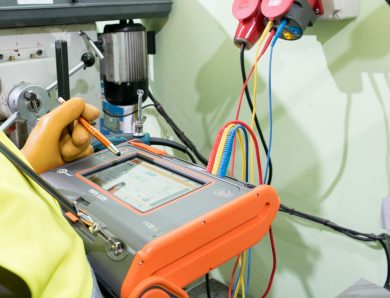
Photo 2. Station tests can be carried out with the Sonel MPI-540 multifunction meter together with the Sonel EVSE-01 adapter
Measuring instruments
Necessary for a complete set of examinations are, of course, the appropriate measuring instruments. They must comply with the requirements of the multi-part EN 61557 standard. It is therefore recommended to use meters from recognised global manufacturers of professional measuring and checking apparatus. There is no doubt that Sonel can be classified as one of these. For more than 25 years, it has been manufacturing professional equipment designed to monitor the safety, technical condition, parameters and quality of the power grid.
The company offers meters that we can successfully use for the above measurements at the charging station:
- Sonel MRU – earthing resistance measurementshttps://sonel.sg/c/earth-resistance-and-resistivity-meters
- Sonel MIC – insulation resistance measurementshttps://sonel.sg/c/insulation-resistance-meters
- Sonel MZC – short circuit loop measurements
- Sonel MPI – multifunctional parameter meters for electrical installations
- Sonel EVSE-01 – an adapter for measuring AC charging stations that is compatible with selected series of Sonel MPI meters
- Sonel LXP – illuminance measurements
- Sonel PQM – power quality measurements
Author: Tomasz Gorzelańczyk, Product Manager, SONEL S.A.
Products mentioned in the article:


No Comment