Use thermal imaging to reduce heat energy losses
In an era of increasingly expensive fossil fuels and soaring prices of electrical power and heat, finding savings is a crucial matter. Tangible benefits on a macro and micro scale are brought about by the reduction of heat energy losses in construction – it is one of the first aspects to be considered when trying to slash the heating bills of your business or home.
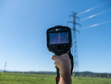
A perfect tool to help locate and identify heat losses is a thermal imaging camera – an instrument which features a microbolometer sensor array that can gauge the level of IR (infra-red) radiation which is a manifestation of thermal energy emission.
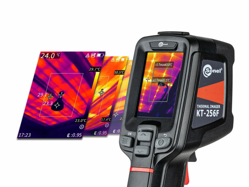
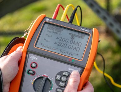
Sonel KT thermal imaging cameras are an excellent choice for both the professional who uses quantitative methods to accurately determine heat losses (Sonel KT-400, Sonel KT-650 and Sonel KT-670 cameras), as well as for amateur users just starting out with IR measurements (Sonel KT-256F, Sonel KT-256 and Sonel KT-200). With a wide range of models and features, everyone can choose a thermal imaging camera to suit their needs.

Table 1. Comparison of the specifications of different Sonel KT series thermal imaging cameras (click to enlarge)
The requirements for thermal imaging measurement in the construction industry for qualitative detection of thermal defects are established in EN 13187:2001. In the case of detached houses, the necessary conditions demand a suitable temperature difference between the interior of the building and the outside air temperature. Much also depends on the thermal insulation of the building – the more effective it is, the higher the temperature difference is required (which is the main factor that determines the heat transmission intensity). Therefore, for thermal imaging measurements of the latest passive energy buildings, the ΔT (temperature difference) must be 30°C, while for a 70-year-old structure without thermal insulation, it is 10°C. In most cases, an acceptable temperature difference will be 15-20°C.
The temperature difference is important because, as said above, it is the main mechanism that ‘forces’ heat from one medium to another through the layer of thermal insulation.
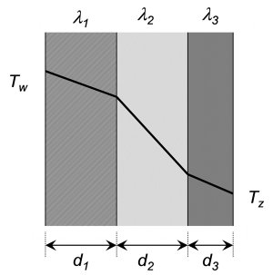
Fig. 1 Heat flow with Newton’s formula
In addition, the EN 13187:2001 standard stipulates that there shall be full cloud cover before attempting a test (for at 10 to 12 h for masonry buildings). This is because the construction materials of buildings have a high heat capacity (they are large ‘heat sinks’). If the weather is cloudless, the building elements are be exposed to sunlight, which can introduce bias and falsify the thermal imaging measurements. What is more, a clear sky affects the thermal imaging for façade parts that have low emissivity (like polished faces).
The same EN standard assumes a maximum air temperature variation of ± 5°C. This is an important consideration during a thermal imaging measurement, as it helps to avoid typical errors and allows a correct interpretation of results, thanks to the standardised measurement conditions.
In qualitative analysis, non-uniformities are sought in the thermal image, or anomalies are called ‘cold bridges’; these are areas of localised decrease in thermal resistance that can be caused by a defect in the thermal insulation of the building or a number of other factors. In the thermal image, a cold bridge is characterised by a lower apparent temperature than an adjacent area whose surface is made of the same material.
Correct identification of the cause of cold bridges (i.e. the root cause of the problem) depends on the experience and knowledge of the thermal imaging operator; hence the importance of sufficient training in practicing the measurement technique itself. Sonel offers training courses in thermal imaging during which our experienced trainers present the theoretical and practical aspects of measurements with a thermal imaging camera.
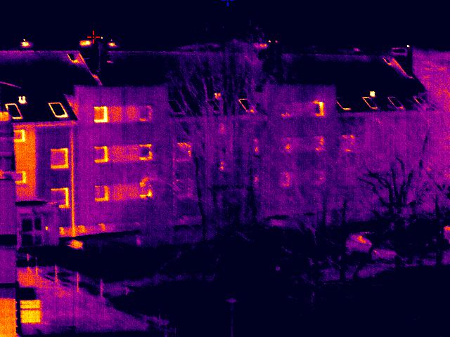
Fig. 2. Thermal image showing a building facade – with a visible heat loss in the area of the ridge and rafters, at the ventilation ducts. Heat loss is also evident in the form of a noticeably warmer façade part around the stairwell
Author: Marcin Magierowski, Sonel S.A.
No Comment