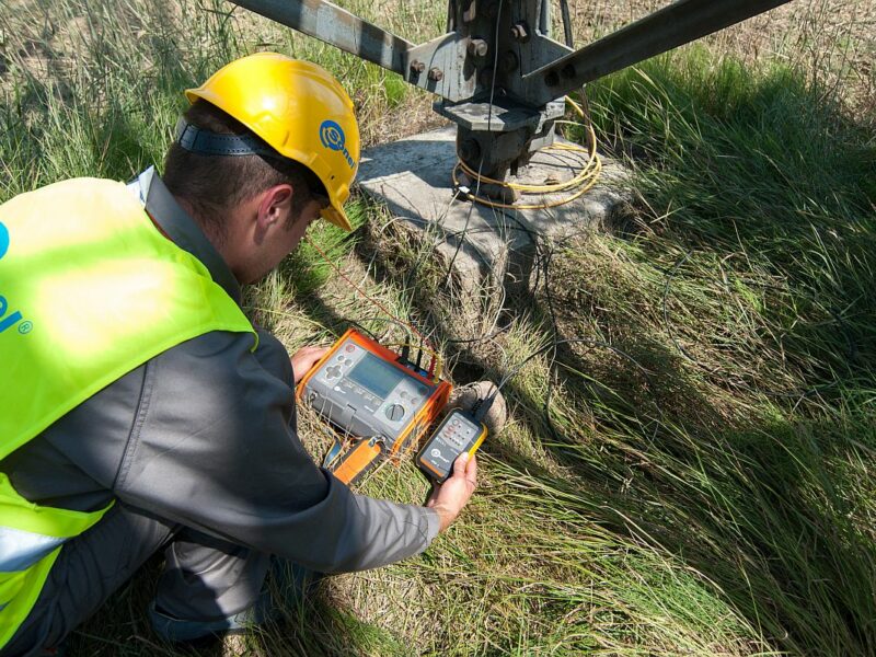
Properly selected meter guarantees correct measurements of resistance to earth
The technical method used widely for measuring earth resistance focuses on the measurement methodology, as well as on skills of the technician and his/her knowledge of the tested earthing circuit, because without it, even the best meter will not guarantee correct readings. On the other hand, even the best and most experienced professional will be unable to carry out proper measurements with incorrectly selected meter or instruments.
Therefore, correctly performed earth resistance measurements require both knowledge and appropriate meter with the necessary equipment. Presented examples show functions and parameters of the meters, assuming that the measurement system has been constructed according to the theory appropriate for the applied method.
3p technical measurement method
The basic and the simplest way to perform the earth resistance measurement using the technical method is the three-pole (3p) method, where the current and voltage circuit is connected to the earthing system with a single test lead. It is necessary to use two auxiliary probes. Current probe (H) is used to create a circuit for the forced measuring current, whereas the voltage probe (S) is an element of the voltage measuring circuit (Fig. 1).

Fig. 1. Diagram of the measuring circuit with 3P method. A – ammeter, V – voltmeter, G – voltage generator, inverter (AC)
According to Ohm’s law, the earth resistance is caused by the current flowing in the circuit and the voltage measured on the tested earthing system. Therefore, the first and actually the most essential feature of the meter for this kind of tests is the inverter power. It is very important to know the current and voltage that may be generated by the device. The test voltage is specified in EN 61557-5 standard and for safety reasons, its allowed value is 50 V RMS. However, if the measurements are carried out in agricultural or animal breeding areas, then the meter must be provided with a selectable voltage option of 25 V RMS . Of course, a meter provided only with the test voltage of 25 V may be used for measurements everywhere, but in most cases (excluding the agricultural areas mentioned above) it is easier to perform measurements using a device, which has more power. Therefore, the best solution is to have a choice of test voltage.
Another key element in selecting proper measuring device is the maximum current of the inverter. Sonel S.A. offers meters with the current of 20 mA or 200 mA. Taking this into account, the purchasing decision should be made consciously, considering its future consequences. During the tests on grounding systems using the technical method, the largest voltage drop is formed on the current probe. Therefore, correct measurements (especially when carried out with a meter of lower measuring current) require the current probe with the lowest possible resistance. This is especially important in soils with high resistivity.
Assuming that the tests are performed with a meter of 20 mA measuring current, taking into account disturbances and difficulties in the measuring point, a situation may occur that the measuring current in the circuit will be too low to measure the grounding voltage. Therefore, for difficult measuring conditions we recommend meters with a high measuring current, which in Sonel instruments is above 200 mA.
The first way to reduce the resistance of the probes is to replace them with longer ones. Standard ground probes offered in a set together with the instruments have a length of approx. 30 cm; but there are longer versions available (Fig. 2). Additionally – in extreme cases – the area of driving the probe in the soils may be saturated with an electrolyte (e.g. water with salt).
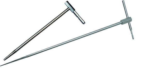
Fig. 2. Probes driven into the ground with a length of 30 cm (standard) and 80 cm (optional)
The use of meters offering only the 3p method and 20 mA current is limited to single earth electrodes (single vertical earth electrodes, cable connectors) and small grounding systems such as small construction objects, e.g. single-family houses (Fig. 3).

Fig. 3. A single vertical earth electrode and a small earthing system
Complex systems require disconnection of all control terminals. Only then, the measurements will be made separately for individual earth electrodes. In systems with foundation earthing electrodes and rings, the measurement is performed for the selected single ground electrode, while the others are checked for their continuity. The described method is implemented in virtually all meters for earthing systems.
The most common errors in the 3p method:
- The ‘H’ probe is driven into the soil too close to the tested earthing system.
- Auxiliary probes are located above conducting elements buried in the ground.
- The voltage probe is driven outside the area of zero potential.
- During tests on large earthing systems (especially at a high soil resistivity), the test current is too low.
4P technical measurement method
The 4-pole (4p) method is basically the same as the 3p method, except for additional test lead in the voltage circuit (Fig. 4).

Fig. 4. 4p technical measurement method
This method provides an option to connect a separate circuit in which the voltage measurement is carried out on the tested earthing system. The actual result of such a test is not affected by errors caused by the resistance of the test leads used to connect the meter with the tested system (test lead with a length up to 2.2 m, which translates into fractions of ohms).
Measurements performed with this method are suitable solution when the meter readouts are lower than 1 Ω. The meter must be firmly connected with the tested earthing system. This firm connection is provided by specially designed cramp shown in Figure 5. Other provisions to be observed and potential errors of this measurement method are the same as described earlier for the 3p method.
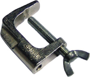
Fig. 5. Cramp
3-pole method with additional clamp
Measurements performed with the 3p method with additional clamp are carried out basically in the same way as with the 3p method. The difference is that the measured current is not the total current in the earthing system, but the current in the selected branch, which is measured with clamp (Fig. 6). It is very convenient solution, as there is no need to disconnect control connections to selectively measure a single earth electrode of the system. A prerequisite for performing this measurement is the absence of metallic connection between the tested earthing system and the rest of the system downstream the attached clamp. So it is impossible to perform proper measurements in places with a ring or foundation earthing system.
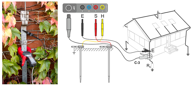
Fig. 6. Measurement with C-3 clamp
Another issue is the complexity of the system. The more ground electrodes in the system, the smaller current value will be measured on one element with attached clamp. Therefore, for large and complex systems (e.g. earthing of low voltage poles), it is necessary to use meters with a large measuring current (200 mA) and ensure the lowest possible resistance of the current probe.
If the field measurements are planned, a high-voltage pole may be used as the auxiliary probe. The probe resistance should be low, especially when there is a high soil resistivity. If the measured current is too small, the meter will indicate results affected by additional uncertainty. In such cases, it would be difficult to identify the cause. Therefore, it is necessary to provide optimal measurement conditions and reduce the resistance of the auxiliary probes. Only after this procedure, possible causes of emerging problems may be analysed.
The variety of constructed earthing systems is large and there are many field objects, where the use of clamp with a hard core (C-3) is not possible due to mechanical reasons. In such cases, the solution may be Sonel ERP-1 adapter with flexible current probe (Figure 7).
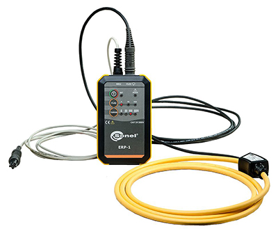
Fig. 7. Sonel ERP-1 adapter with flexible current probe
This product is intended for power utilities and companies providing services for professional power industry. Sonel ERP-1 adapter used with Sonel MRU-120, Sonel MRU-120HD, Sonel MRU-200 and Sonel MRU-200-GPS meters enables the user to perform clamp measurements in places previously unsuitable for such testing. The adapter allows user to measure earthing systems of lattice poles without disconnecting their control connections and switching off the line.

Fig. 8. ERP-1 on a concrete pole and during a measurement on a lattice pole
This kit may be used to attach current probe to large objects, e.g. two concrete poles with MV/LV transformer installed on them. An additional advantage is a proprietary algorithm of Sonel S.A. used by Sonel MRU-200 and Sonel MRU-200-GPS meters. It checks the current direction for the individual measurements. This feature enables the meter to identify damage involving torn (or totally corroded) steel strip (hoop) attached to the ring earthing of such a pole. This is a unique feature, not offered in any other earth meter available on the market. In addition, these two meters have automated procedure of calculating the earth resistance of a lattice pole, eliminating the need to manually convert the partial results in order to obtain the resultant resistance.
The most common errors in the 3p method with additional clamp
The most common error made when using the clamp is the belief that they are suitable for all earthing systems. However, this method is adequate only for multiple earth electrodes without the ring earthing! The clamp will not provide proper result for systems with a single earth electrode, foundation or ring earthing system. For large (complex) systems, it is necessary to use meters with the largest measuring current available, as well as other accessories allowing the correct structure of the measurement system (test leads and probes of adequate length).
Another problem may result from attaching the clamp to artificial earthing, where the point of meter connection includes (in addition to clamps) also other conductive parts – e.g. concrete, reinforced LV poles.
The example shown on Figure 9 presents such a situation. Clamp attached to the earthing system detect only a part of the current causing the measured voltage drop. The result will be an indication of resistance higher than the actual value. In terms of protection against electric shock this situation is harmless, but if the data obtained will be used to decide on upgrading the earthing system, this may generate unjustified costs.
The solution, not affected by this phenomenon, is the use of flexible current probe and attaching them to the entire pole with its earthing system.

Fig. 9 Low voltage pole. Incorrect measurement with C-3 clamp
Two-clamp method
Principles of using the two-clamp method, depending on the type of tested earthing system, are substantially the same as for the 3p method with additional clamp. However, one feature of this method must be taken into account: the measurement provides the value of measured earthing system increased by the resultant resistance of the earthing system.


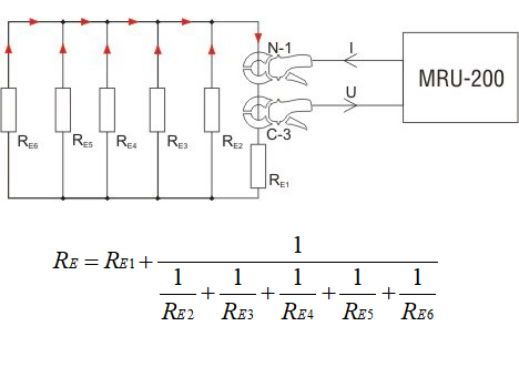
Fig. 10. Two-clamp method – example
For measurements in systems with foundation earthing or ring earthing, this method cannot be used to test the earthing resistance. However, it is very convenient for testing the continuity of metallic connections in the entire earthing system (horizontal air terminal- connecting conductors- grounding wires – connecting conductors – earth electrodes).

Fig. 11. Two-clamp measurement Testing the continuity of conductors in the grounding system with ring
Impulse method
Another aspect to be considered when selecting the measuring device is its versatility. When measurements of earthing systems include also testing the lightning protection systems, it becomes essential for the device to offer the option of their correct performance. With this type of measurements, tested parameters include earthing impedance or dynamic resistance.
The purpose of lightning protection systems is to discharge electrical load caused by lightning to the ground. This load is dynamic, therefore the method of testing the lightning protection should be adequate. Earth resistance meters Sonel MRU-200 and Sonel MRU-200-GPS fully meet this requirement.
The impulse method, applies completely different parameters than the technical method. The meter generates a pulse with a precisely defined shape, reflecting the shape of the lightning impulse.

Fig. 12 The shape of test pulse in the impulse method
Pulse parameters are defined by two numbers: T1 – rise time of pulse leading edge and T2 – time to half-peak Described Sonel meters provide a selection of three pulse shapes: 10/350 μs, 8/20 μs and 4/10 μs. Pursuant to EN 62305, the pulse with a shape of 10/350 μs is typical for the first stroke of the lightning current. Pulse 8/20 μs is used to test the effect of discharges on devices. Pulse 4/10 μs of this shape is firmly rooted in the practice of measurements.
Summary
The decision on selecting an instrument for testing the earthing systems must be taken after careful consideration and identification of actual needs. The meter, as any other tool, will do its job only when it is chosen correctly and adequately for the planned measuring task. The decisive element is obviously the functionality of the meter, but as mentioned above, the key features may be accessories and power of the inverter used. Undoubtedly, professionals and companies in the power industry should choose high-power meters. This is a key condition, as their working areas include the toughest field conditions. Equally important is the equipment and accessories, such as long test leads (e.g. 100 m or 200 m), suitable for testing extensive earthing systems, e.g. in power stations and sub-stations.
The information provided in this text is intended to draw attention of the reader to the aspects of earth resistance measurements, which are often overlooked, resulting in the purchase decisions based only on the price of the measuring device. As a result, adverse effects of such decisions are discovered unfortunately some time after the purchase. Remember that properly selected instrument is a guarantee of comfortable, time-saving and satisfying work, which provides accurate measurements of earth resistance.
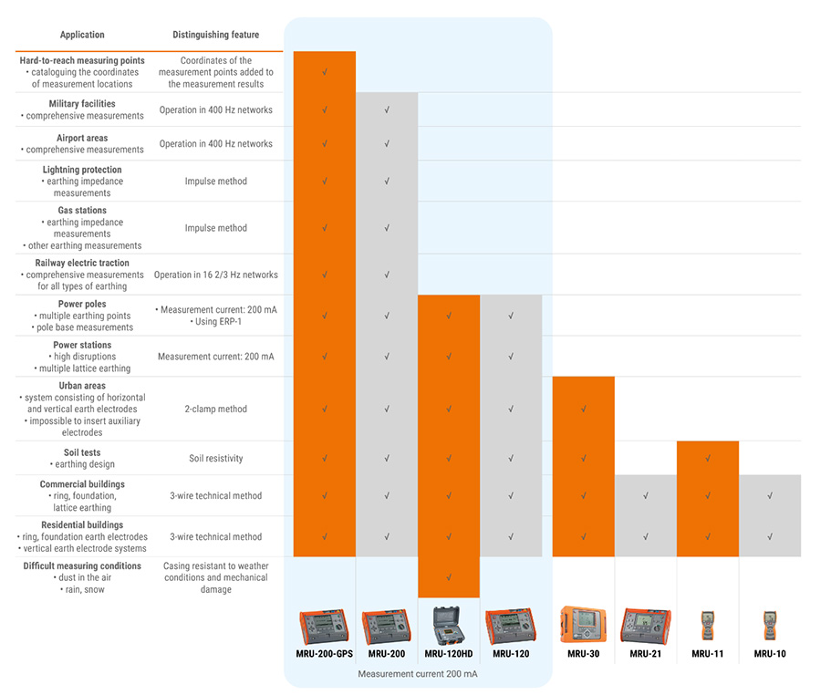
Fig. 13. Comparison of earth resistance meters MRU series by SONEL S.A.
Authors: Roman Domański, Adam Szczepanik – Sonel S.A.
Products mentioned in the article:


No Comment