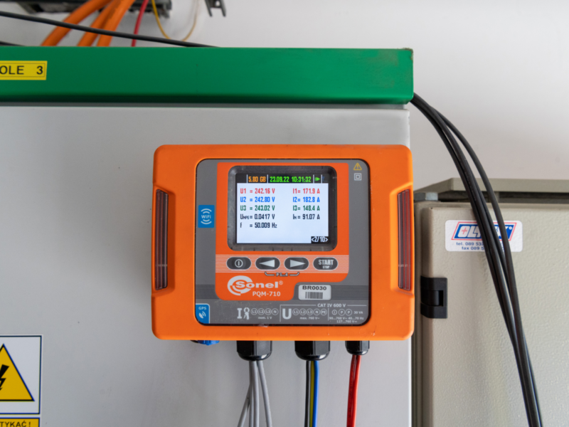
Unjustified tripping of overcurrent protection
The functioning of energy distribution systems ensuring both reliability and durability in normal and emergency states, requires the use of protective elements. Proper selection of parameters and settings requires detailed knowledge of the character and variability ranges of individual parameters. The wrong selection may be indicated by unjustified activation of the protection.
Description of the identified problem
In an industrial facility, one of the machines behaves quite unusual. During its randomly occurring switching on, its overcurrent protection C16A is triggered. Reactivating it does not have the same effect and the machine starts without any problems. The device contains many actuators in the form of servos ensuring the implementation of technically required functionality. The recording allowing to capture a random phenomenon had an averaging time (interval) of 10 s.
Measuring equipment used
- Sonel PQM-702 Power Quality Analyzer (see the product successor Sonel PQM-710)
- Set of C-5A current clamps
- Sonel Analysis software
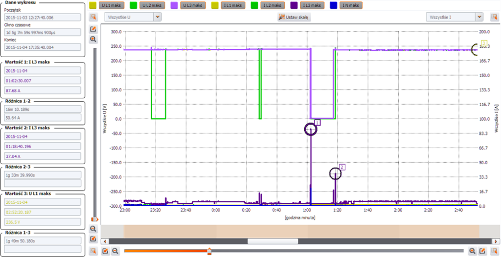
Fig. 1. The image of voltages and currents recordings of the machine start-up operation
Marker 1 in Fig. 1 shows one characteristic current jump, different from the others, up to the MAX20ms value, approx. 87.68 A, which caused unjustified tripping of the protection. Subsequent switching on and starting (Marker 2) shows the current level of 37 A. The 5 A level is not exceeded at all other times.
To follow the moment we are interested in more precisely, we will enlarge the selected part. On the enlarged registration section (Fig. 2) some very important information is visible. The protection was turned off after a short stoppage of the machine (See 1.), caused by a momentary voltage failure. The phenomena of significant increase of the instantaneous current takes place in the L3 phase. The MAX20ms current reached the value of 87.68 A while currents in the remaining phases ranged at 20 A level. One of the loads was a high power isolating transformer powered from the L3 phase. Another power-up (See 2.) during which the protection did not trip. The occurring increases in the inrush current in L3 are associated with the occurrence of the L2 phase voltage. There was also a large delay between the switching on of individual phases.
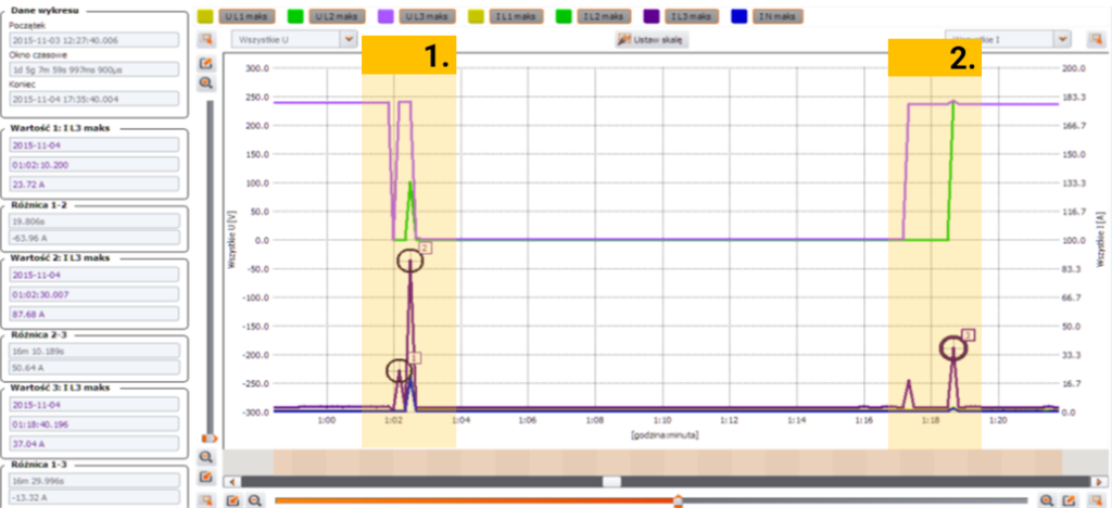
Fig. 2. Picture of voltages and currents during operation and activation of the protection
Initial conclusions
- One of the loads of the tested receiver is a single-phase 700 kV isolating transformer switched on with a common switch.
- L3 phase transformer starting states are random in nature and may induce the observed phenomena depending on:
- core magnetization state at the moment of switching on,
- instantaneous voltage at the moment of switching on.
- Large symmetrical components (Figs. 3 and 4) indicate non-linear phase loads (Fig. 2), which may additionally contribute to high inrush currents.
- A suspicious delay in phase activation may indicate a mechanical failure of the switch.
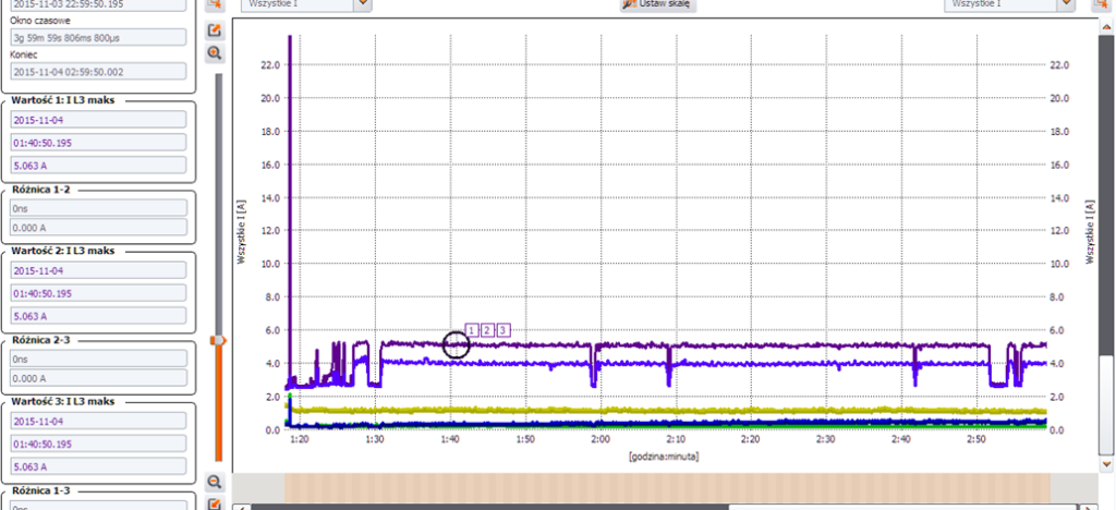
Fig. 3. Current image during normal device operation
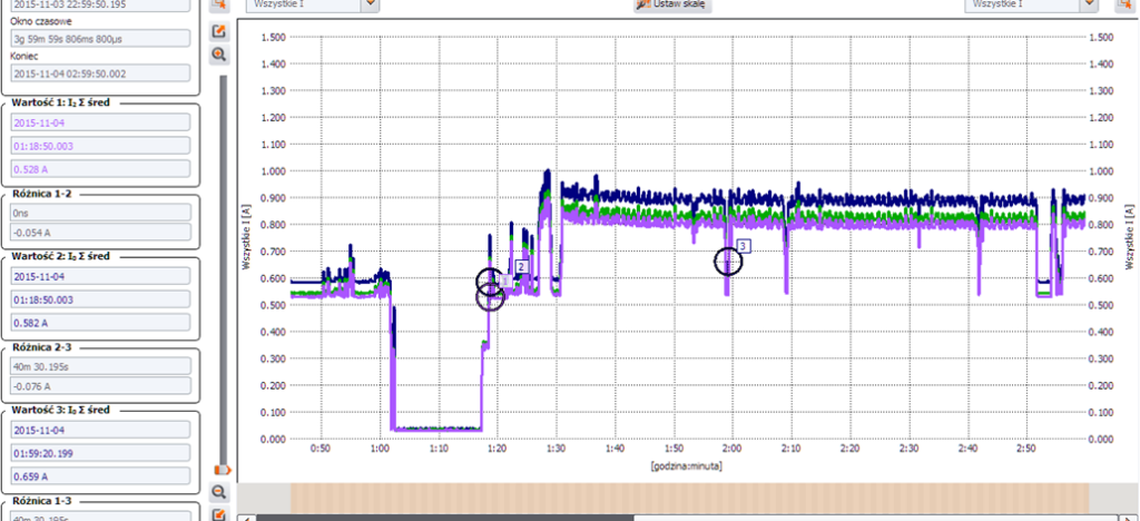
Fig. 4. The symmetrical components of the currents during operation almost match
Conclusions:
When switching the device on, transformer inrush currents occur, against which the C16A protection is not resistant, while meeting other conditions.
Recommendations:
- The switch should be inspected for mechanical damage.
- It is necessary to diagnose in detail (quick recordings with oscillograms) the processes of switching on the machine, focusing on simultaneous switching, or the defectiveness of the load-constituting elements, after the inspection.
- It is necessary to verify the selection of the protection in terms of cooperation with inductive loads in the direction of DxxA instead of C16A.
Author: Krzysztof Lorek
Products mentioned in the article:


No Comment