Safe Earthwork: Avoiding Damage To Buried Utilities
Construction and earthworks are increasingly being carried out in locations densely occupied by buried utilities. How to really prevent their damage and avoid costly repairs? One solution is cable, wiring and buried utility locators which enable safe construction and earth moving.
Nearly construction projects involve some earthwork. A result is usually the need to adapt new construction features to the buried utilities existing on site, which means building next to, over, or under the utilities in operation, including power grid components. This greatly complicates the development of construction projects.
More projects mean higher risk of utility damage
Without precise planning, a project may result in accidental damage or interruption of services provided by utilities. When either happens, the project budget is overrun, usually by a considerable amount, for repairs.
The rapid growth of the new construction sector and the increasing number of projects drive up the risk of damage to buried utilities. Another problem is the lack of consistency between specific projects. For example, the replacement of sewerage or water mains is often done right after a road repair, which is a symptom of insufficient planning and a lack of forward thinking. A result is the difficult future expansion of utilities with any cost efficiency.
The density of buried utilities has been growing, and not just in heavily built-up urban areas. The trend will continue to grow, as nearly all utilities today are planned to be buried features. One reason for it is the functional and aesthetic values, because overground or surface utilities is becoming unacceptable in the modern urbanscape.
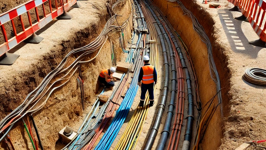
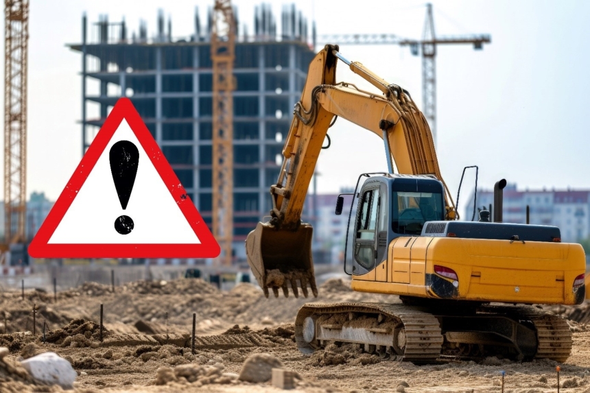
Image 1. Increasing density of buried utilities
Increasing demands on power networks
On top of this is the challenge of retrofitting ageing power networks by relocating overhead lines into the ground. The objective of retrofitting is to improve the reliability and safety of electrical power supply; a logical choice, given the climate change. Overhead networks, especially those built nearly fifty years ago, were not designed for modern levels of loads and extreme weather phenomena. Rising temperatures and the increasing frequency of hazardous weather events make the upgrade of power networks even more urgent.
Causes of damage to buried utilities
The foregoing suggests that the number and density of buried utilities continues to grow; sooner or later, an earthwork project will have to tackle a buried line or pipe. The key question is: Can damage be avoided? The answer is yes, as long as proper precautions are in place.
The most common causes of damage to buried utilities include:
- failure to review plats;
- time pressure;
- human error;
- inaccurate mapping of utilities on plats;
- utility networks or portions thereof missing from plats;
- limited accuracy of utility mapping on plats.
A common mistake is to skip the review of land survey plats and disregard potential conflicts with buried utilities. In practice, this is usually caused by haste or pressure from superiors, although it can lead to costly mistakes. It makes all the sense to take a bit more time and prepare the work properly, even at a risk of slight schedule overrun. In the long term, the costs will be much lower than repairing damaged utilities.
A key to minimise the risk of errors, careful preparation of the work and training of personnel, especially the excavator operator. Firstly, excavator operators for the job need proper induction and enough rest to markedly reduce the risk of work errors. Secondly, it is important to educate using the lessons learned from real-life accidents (like an explosion caused by damage to an earth gas service line), as it helps prevent hazards from repetitive and reckless behaviour of operators.
Some utility damage incidents are a result of past errors made by the authors of references, plans and maps a project needs to use. True, such aspects are beyond our direct control; nevertheless, it is still important to mind their potential consequences. Reference data, even if true, can be restricted by a poor survey accuracy. The error tolerance of utility locating can reach up to several meters; in extreme cases, a service line attempted to be found is actually somewhere else than on the map, like the other side of the street.
How can the risks from mapping errors be minimised? It is crucial to double check and verify the maps and plans before the actual work begins. The first step is to use free online services with land survey data or plats (maps) that allow you to check for buried utilities on the site of the planned project. This helps with better preparation for the project implementation and potential risk identification.
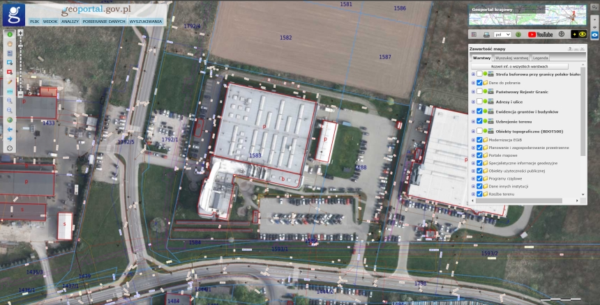
Image 2. Survey data check and verification using the land survey portal www.geoportal.gov.pl
Reliable plan verification using cable locators
Another way to verify plats and plans is to survey the project site with cable locators. The site should be surveyed in two steps:
- Verify the actual course of buried utilities and features that are shown on land survey plats.
- Search the site for unmapped, defunct, or post-demolition utility parts.
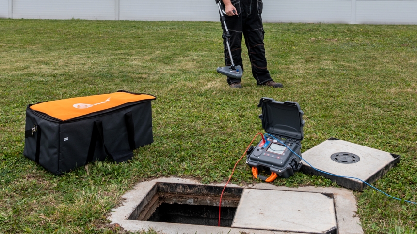
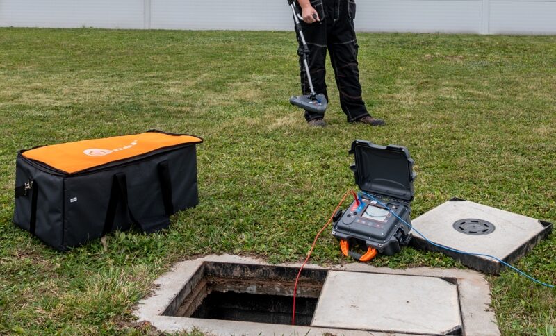
Image 3. Construction site survey done with a Sonel LKZ-2500 locator
The first step is straightforward, as you know where to look for the mapped utilities. It is best to use active-mode locators that input signals into buried lines and trace their course. Large locators should be used for the task, as they are designed for field use and deeply buried utilities. The tracing signal transmission method is also important, as the location accuracy depends on it.
Three transmission methods
There are three basic methods of tracing signal transmission:
- Galvanic: the transmitter is directly connected to the object being traced and its conductive part;
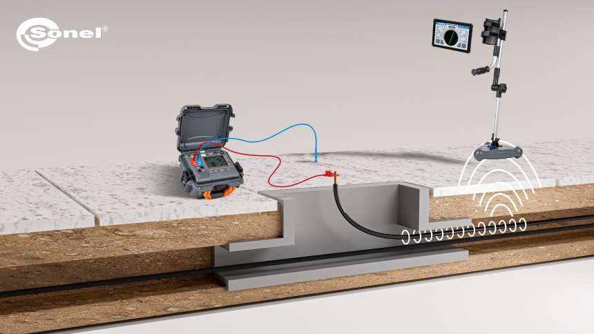
Image 4. Galvanic signal transmission
- Clamp: the tracing signal is induced using transmitter clamps, which does not require any physical interface (the traced cables can be live and dielectrically insulated).
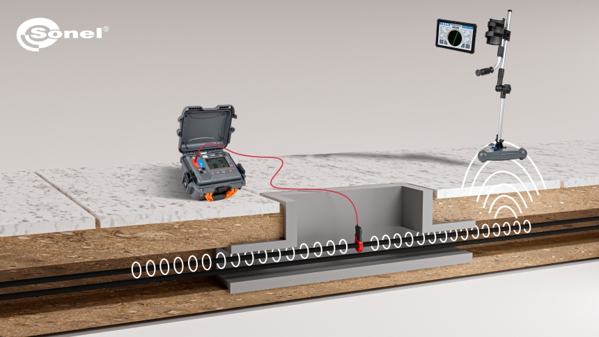
Image 5. Clamp signal transmission
- Inductive: the integrated antenna of the locator transmitter induces the tracing signal in all conductive objects located below and in the direction shown on the transmitter.
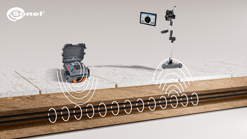
Image 6. Inductive signal transmission
The galvanic signal transmission is the most effective, as it allows the strongest tracing signal input that directly depends on the current level generated in the traced object. The tracing signal can be further amplified by grounding the other end of the cable being traced, which significantly improves the locator’s performance.
Locating non-conductive utilities
Unfortunately, not all buried utilities are electrically conductive. For locating PVC pipes, dedicated accessories can help:
- A spooled transmission cable, which can be launched into the piping like a pilot wire. When the cable is connected to the locator’s transmitter, the piping can be precisely traced, not unlike a power cable.
- Transmitter probes, which are small output heads that can be attached to a pilot wire and launched into the piping, followed by tracking the probe with the locator’s receiver.
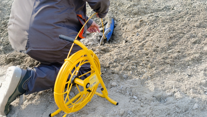
Image 7. Locating non-conductive utilities using a dedicated transmission cable
Surveying for unmapped utilities
The second step is surveying the site to detect all buried utilities, which requires much more care and experience. The locator operator must be skilled in interpreting the feedback signals, a condition crucial to the success of the whole location process. There are two types of the surveys:
- In-service utility tracing: finding unmapped power cables, data lines, and gas pipes;
- Defunct conductive utility tracing: finding utility features that have been out of service and can be potentially in conflict with the project’s work.
In-service utilities can be traced the fastest in passive locator modes, in which the detector head is used only. Here, these modes are used most often:
- POWER: enables detection and tracing of cables operated at 50 or 60 Hz mains voltage
- RADIO: tracks all signals in the selected frequency band.
Utility surveys in passive modes are usually done along straight parallel lines about one metre apart and heading square to one edge of the area. The operator moves along each line, looking for signals. If a stable tracing signal is found, its location on the ground is flagged. The resulting chain of flags is used to trace where the detected utility line goes.
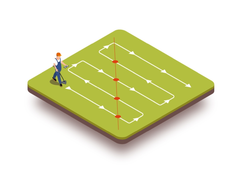
Image 8. Passive-mode utility survey: first pass
After the first survey of the site, the process needs to be repeated along parallel lines which go square to the lines surveyed in the first pass. This provides a survey grid with square cells, each one metre long. This method improves the likelihood of locating utilities and the accuracy of their mapping.
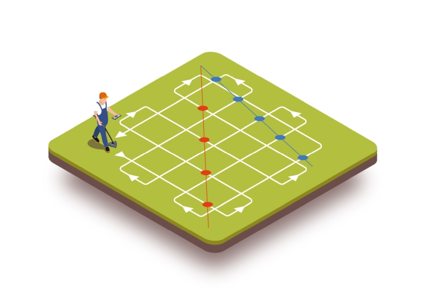
Image 9. Passive-mode utility survey: second pass
Modern locators and survey grids
Survey grids are especially important for tracing with legacy locator hardware which, due to their limited number of antennas, may pose difficulties in tracing objects parallel or square to the line surveyed with the detector. The processing limitations of such legacy hardware affect the accuracy of readings and reliability of tracing.
Modern locator detectors with multiple antennas or 3D antennas, like the Sonel LKZ-2500, make survey grids obsolete. It is enough to walk along the perimeter of the surveyed area to detect buried utilities, if present. The 3D antennas allow feedback signals to be picked up no matter the angle of deviation from the line of the trench.
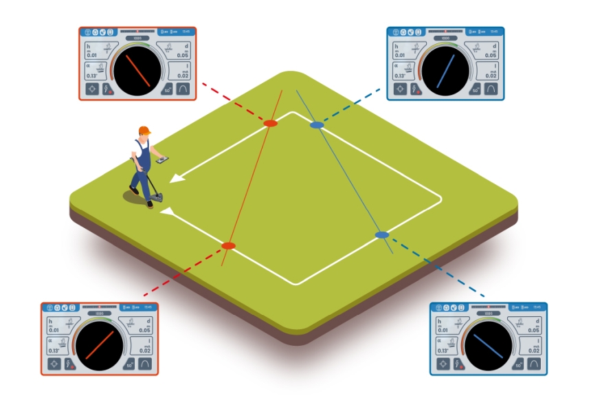
Image 10. Perimeter utility survey. A case of a cable crossing the project site
This significantly reduces the time required to trace out potential buried utilities. However, to increase precision, the process should include additional rounds which gradually take the locator away from the perimeter and into the surveyed area. Repeating the tracing in several places perpendicular to the routes in the first pass minimises the risk of missing buried utilities which start or end in the area of interest.
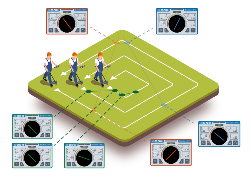
Image 11. Perimeter utility survey with an inward square track. A case of cables present only within the project site
An essential task before starting to move earth is to make an extra round with the detector along the planned trench. This walk should be done first in the POWER mode and repeated in the RADIO mode, as each of these is designed to pick up a different feedback frequency.
Defunct (inactive) utilities can be found using the RADIO mode if they bounce back interference or signals induced by other objects. Examples include buried earthing strips and utility marker tapes.
Short runs of utilities can be difficult to detect, though. The tracing procedure should be then repeated in induction mode and with two operators: one operator walks along the planned trench and scans with the detector, while the other operator walks in parallel using the transmitter in the induction mode. This ensures the highest detection performance for defunct utilities. The survey walks should be repeated in perpendicular to the square edge of the surveyed area.

Image 12. Active induction mode utility survey. A case of defunct, inactive or signal-less buried utilities
Under favourable conditions, spot checks can also be done by one person using a detector equipped with 3D antennas and a mobile app. This tech allows the operator to place the detector in one spot and move around it in circles with the transmitter, reading the tracing results on a tablet. The detector must remain stationary and the transmitter must be moving to ensure a full spectrum of the survey. Transmitters that are oriented not in the direction of signal induction may fail to trigger a feedback from the utility features scanned for.
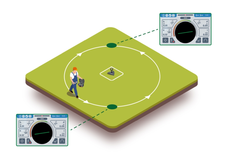
Image 13. Active induction mode spot survey
Remember that it is essential to start the earthwork after scanning the area along the planned trench or within the planned earth cut and that the survey grid method has the lowest likelihood of missing.
Maps, locator and common sense
Not all cables, such as data/telecom or fibre optic cables, can be detected using cable locators. The same goes for some gas service lines and non-conductive services. It is always key to study the plats and verify their features in the field. Common sense is recommended: a sink in the ground along the planned earthwork area can hide a buried utility line.
Author:
Bartosz Fijałkowski, MSc. Eng., Sonel S.A.

No Comment