Measurements of Short Circuit Loop Impedance in Photovoltaic Farms in IT Networks at Voltages up to 900 V AC
Loop impedance measurement on photovoltaic farms in IT systems with voltages up to 900 V AC is one of the greatest challenges in modern PV system diagnostics. High voltages, the specifics of IT networks, the presence of inverters, and the large scale of installations require not only specialized equipment, but also knowledge, experience, and a precisely planned measurement methodology. How can such measurements be carried out safely and effectively? Which standards must be met, and what should be paid particular attention to?
Introduction
The dynamic development of the renewable energy sector, in particular photovoltaics, has greatly increased the number of large PV installations. Despite periodic fluctuations in the energy industry, investments in photovoltaic farms remain at a high level. At the same time, there is a growing demand for precise diagnostics of installation operating parameters, including the measurements of short circuit loop impedance (ZS). This parameter is essential for verifying the correct operation of the electric shock and short circuit protection systems and the compliance of the PV system with design specifications.
However, short circuit loop impedance measurements in photovoltaic farms, particularly those operating in IT network systems, face many difficulties due to the specific characteristics of such installations, such as:
- the presence of inverters that may interfere with classic measurement methods,
- variable energy generation conditions arising from the fluctuations in solar radiation levels, which affects the stability of measurement results,
- large distances and long cable lines, typical of PV farms spanning several hectares and capacities reaching several hundred MWp (approximately 1.5 ha of land is required per 1 MWp of installed capacity),
- using an IT network system in which the short circuit loop impedance and earthing method are fundamental for the effectiveness of electric shock protection,
- the actual voltage at the inverter output exceeding 800 V AC, which limits the availability of dedicated measuring devices.
This article discusses the nature of short circuit loop impedance measurements in IT systems of photovoltaic farms, the measurement methodology and the interpretation of results in systems with voltages up to 900 V AC.
2. Should short circuit loop impedance measurements be performed in IT networks at PV farms?
Electrical measurement professionals often raise doubts regarding the necessity to perform the measurement of short circuit loop impedance (ZS) in photovoltaic installations operating within IT network systems. Another issue is the reliability of the obtained results in the presence of inverters, which may affect the stability of measurements. Additional challenges also arise from the other issues mentioned in the introduction.
The answer to the question is clear: yes, the measurement of short circuit loop impedance is necessary and should be performed in a comprehensive manner. Furthermore, a single measurement might not be sufficient; multiple tests should be performed under various simulated, plausible scenarios to gain a full understanding of the network parameters and the effectiveness of the protection systems in place.
The basis for conducting the said tests are the applicable standards, including:
- HD 60364-6 – specifying the requirements for acceptance and periodic testing of electrical installations,
- HD 60364-7-712 – Low-voltage electrical installations – Part 7-712: Requirements for special installations or locations – Solar photovoltaic (PV) power supply systems
- HD 60364-4-41 – Low-voltage electrical installations – Part 4-41: Protection for safety – Protection against electric shock
- EN 62446 – relating to the requirements for the tests, inspection and testing of photovoltaic systems
The requirements of the above standards should be met to ensure installation safety and verify the compliance of the tested system with design specifications. The following sections of the article discuss the specific aspects of performing impedance measurements in IT networks at photovoltaic farms.
3. IT network system
The IT network system is used where maximum personnel safety and high power supply reliability are required – also in emergency situations, which would trigger overcurrent circuit breakers in TN or TT network systems.
The configuration of an IT network is of particular importance; all live parts (L1, L2, L3, and, if present, N) are isolated from earth or connected to it through a high impedance (e.g., a spark gap or a resistor of 1500 Ω), while exposed conductive parts are directly earthed.
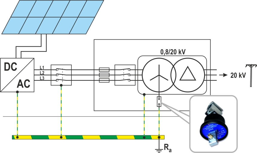
Fig. 1. Diagram of a PV installation system with a transformer in an IT network. The neutral point of the transformer is earthed through a spark gap
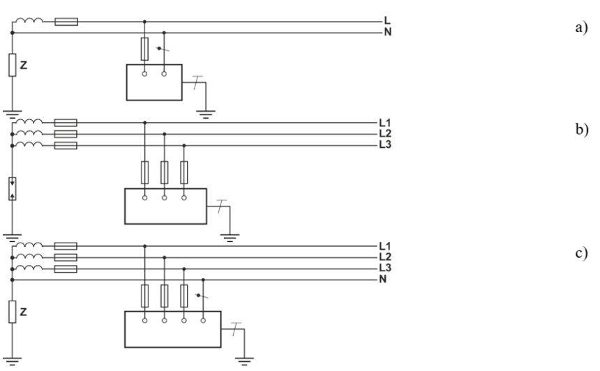
Fig. 2. Possible IT network configurations as per the IEC 60364-1 standard:
a) 1-phase IT system with the transformer neutral point earthed through high impedance Z
b) 3-phase IT system without neutral conductor, with the transformer neutral point earthed through a spark gap
c) 3-phase IT system with neutral conductor, with the transformer neutral point earthed through high impedance Z
To ensure effective operation of an IT system, exposed conductive parts must be properly earthed. This can be done in several ways: individually, in groups, or collectively.
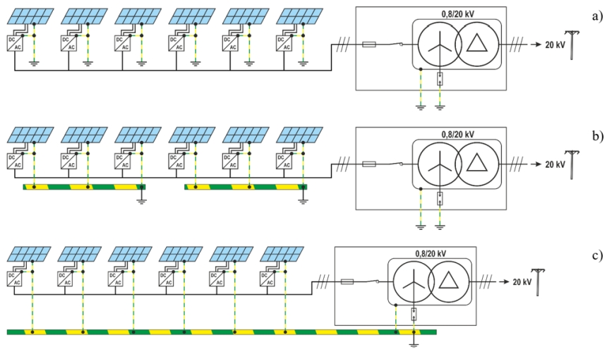
Fig. 3. Possible methods for implementing protective earthing in a photovoltaic installation:
a) individual earthing, b) group earthing, c) collective earthing
Protection of exposed current-carrying parts is provided by connecting these parts to earthing system – see Fig. 1 and Fig. 2.
4. Monitoring the status of IT network operation
The following monitoring and protection devices may be used in IT systems:
• IMD – insulation monitoring devices,
• RCM – residual current monitoring devices,
• IFLS – insulation fault location systems,
• OCPD – overcurrent protective devices,
• RCD – residual current devices.
The standard in IT networks is to use a device that constantly monitors the insulation in relation to earth – IMD ( Insulation Monitoring Device). IMD detects a drop in insulation resistance and indicates a fault (e.g. via a visual and/or audible alarm), but does not immediately switch off the power supply. This allows the system to continue operating (maintaining power supply continuity) while the fault is addressed without downtime. However, in extreme cases, failure to react to the first fault may lead to a second fault, which results in a phase-to-phase short circuit and forces the overcurrent protection to disconnect the power supply.
Thanks to IMD, the IT system ensures high power continuity, but requires regular monitoring and a quick response to the first fault to prevent a more serious fault.
More information about the structure and operation of IT networks can be found in industry literature, e.g. in the publication “Ochrona przeciwporażeniowa w sieci o układzie zasilania IT” (Electrocution Protection in an IT Power Systems) by mgr. inż. Julian Wiatr.
5. The impact of the IT system characteristics on short circuit loop impedance measurements
The proprieties of the IT system are key for the methodology of measuring short circuit loop impedance in photovoltaic installations. Unlike TN systems, where a fault of a phase conductor with (a) an exposed conductive part or with (b) the protective conductor of a circuit/device results in high fault currents, in an IT network the first fault to the exposed conductive parts generates only small capacitive currents (usually a few milliamperes).
A brief explanation is in order here. Capacitive current results from the capacitance of cables (the other two operational lines) and receiving equipment relative to earth. In an IT system, the transformer’s neutral point is not directly earthed, so in the event of a single fault (e.g. a phase-to-earth fault), the fault current is not limited by earthing impedance, but is primarily determined by the line-to-earth capacitance. For this reason, traditional measurement methods may not provide reliable results, and the interpretation of the obtained values requires an in-depth analysis of the network configuration at the time of the test.
It should be emphasized that a fault in the circuit does not necessarily have to be a metallic phase-to-earth short circuit; in this context, HD 60364-4-41 refers to a fault involving an exposed conductive part. In this article, the terms “earth fault” and “ground fault” will refer to the meaning given in the standard. It is worth noting that the terms “first” and “second earth fault” are often used in industry literature; however, this article will follow the terminology adopted in the standard referenced above.
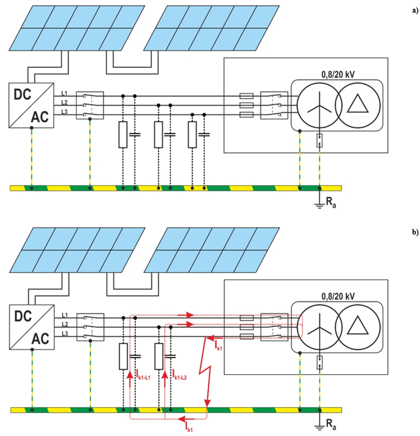
Fig. 4. IT network operation a) under normal conditions, b) at the first fault in the circuit
6. First fault in the circuit
A single fault in the circuit does not cause large fault currents because they close through the capacitances of the remaining phase conductors relative to earth and through the PE protective conductor, forming a closed circuit within the galvanically connected network. The value of this current does not depend on the fault location, but on the current configuration of the entire installation.
To ensure effective electric shock protection in an IT system after the first fault in the circuit, the following condition must be met:
Ra·Ik1 ≤ 50 V AC
Ra·Ik1 ≤ 120 V DC
with:
- Ra – total earth resistance and protective conductor resistance for exposed conductive parts [Ω],
- Ik1 – first fault current [A], accounting for leakage currents and earth impedance.
If the exposed conductive elements are properly earthed, the first fault in the circuit does not pose a shock hazard, and therefore the damaged circuit is not immediately disconnected (this condition is only signalled by the IMD/UKSI).
An IT network in the first fault condition may resemble a TN or TT network, depending on the earthing method of its components (see Fig. 3).
- TT – when earthing for individual devices is made separately or in groups – Fig. 3a, Fig. 3b. See an example of transformation in Fig. 5a.
- TN – when all devices are connected to a common earthing system – Fig. 3c. See an example of transformation in Fig. 5b.
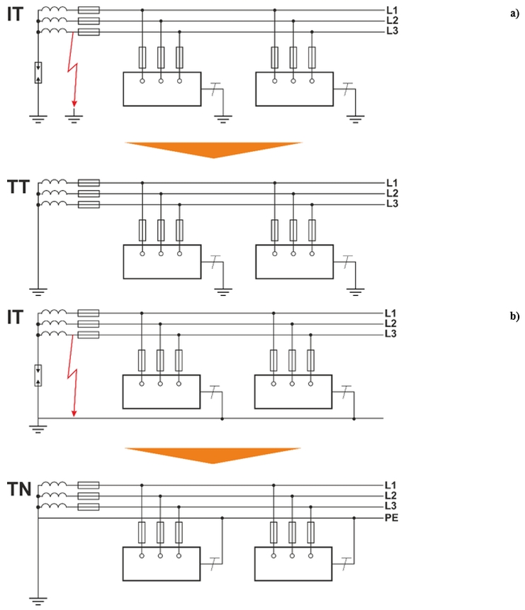
Fig. 5. Transformation of the IT network as a result of the first fault:
a) in the TT system (individual or group earthing – cf.. – Fig. 3a, Fig. 3b), b) in the TN system (collective earthing – cf. Fig. 3c)
To correctly determine the required automatic power disconnection time, in accordance with the requirements of HD 60364-4-41, the PV installation designer must specify into which system the IT network will transform after the first fault occurs in the circuit.
According to this standard, for final circuits with a current not exceeding:
- 63 A for supply circuits equipped with at least one socket outlet,
- 32 A for circuits supplying only permanently connected electrical equipment
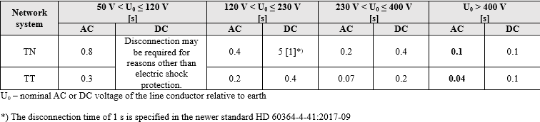
the maximum disconnection time is given in Table 1. The same standard states that for TN and TT systems with final circuits carrying currents exceeding the above values, the disconnection time must not exceed:
- 5 seconds for TN networks,
- 1 second for TT networks.
We treat a large photovoltaic farm (capacity of 1 MWp) as a system in which the currents in the power supply circuits exceed 63 A, so a maximum disconnection time of 1 second or 5 seconds is assumed.
Tab. 1. Required automatic disconnection times in accordance with the requirements of HD 60364-4-41 for sockets with a rated current of ≤63 A and permanently installed receivers with a rated current of ≤32 A
7. Second fault in the circuit
Unlike the first fault in the circuit, the second one leads to the formation of a classic short circuit loop, generating a much higher fault current. Therefore, measuring the short circuit loop impedance in an IT network requires the analysis of various scenarios, taking into account different earthing configurations and possible fault conditions.
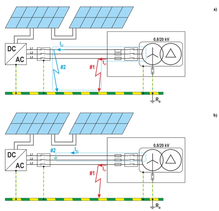
Fig. 6. Fault current in a collectively earthed IT system during a double fault:
a) two faults: L3-GND (#1), L1-GND (#2), b) fault of L3-GND (#1) and phase-to-phase fault L1-L2 (#2)
A. Second fault in the IT network considered as a TN system
If all conductive parts in the system are connected to a common protective conductor (Fig. 3c), then during a second fault in the circuit the fault current is determined by the short circuit loop impedance. It is absolutely necessary to assume the worst possible scenario, i.e. the simultaneous occurrence of two faults that may occur in different circuits. An example would be a situation where a fault of one phase with an exposed conductive part occurs at an inverter extremely distant from the transformer, and a fault of another phase occurs at another inverter (also at a significant distance from the transformer), with the fault current for these two faults flowing mostly through different sections of the equipotential bonding. This refers to the system version with a single equipotential conductor, as shown in Fig. 3c. In this configuration, the length of the fault path will double (which is why the value 2 is in the denominator in both formulas).
IT systems come with a neutral conductor (see Fig. 2), but systems without a neutral conductor are more common. Both cases must be considered using the appropriate formulas.
| IT system without neutral conductor | IT system with neutral conductor |
| ZS ≤ U / (2·Ia) | Z’S ≤ U0 / (2·Ia) |
with:
ZS, Z’S – short circuit loop impedance consisting of the phase conductor and the protective conductor (ZL+ZPE),
U0 – nominal voltage between phase and neutral conductor (UL-N),
U – nominal voltage between phases (UL-L),
Ia – current required to trigger the protective device within the specified time, as per the requirements for TN networks (see Section 6 of this article).
B. Second fault in the IT network considered as a TT system
If, in an IT network, exposed conductive parts are connected to earthing individually or in groups (Fig. 3a, Fig. 3b), then it should be treated as configuration that will become a TT system. To implement automatic power supply disconnection, regardless of the protection used (overcurrent or residual current devices), the following condition for protection against electric shock must be met:
Ra ≤ UL / Ia
with:
Ra – resistance of the earth electrode and protective conductors,
UL – permissible touch voltage (typically 50 V, or 25 V / 12 V in high-risk environments),
Ia – current that causes the automatic trigger of the protective device within the required time for TT networks (see Section 6 of this article).
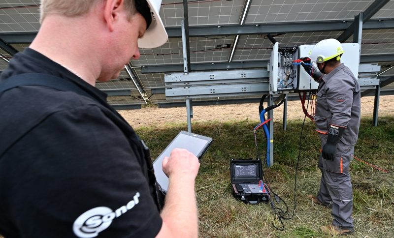
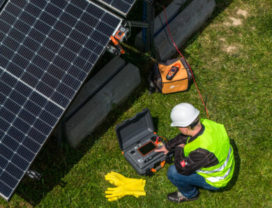
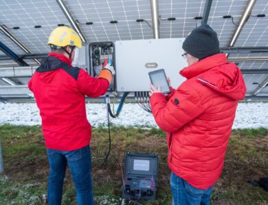
8. Measurement procedure
After reviewing the design documentation (diagrams are usually available at the transformer station) and obtaining all the necessary information, you can start taking measurements.
But are we sure about that? Do we have the appropriate meter, personal protective equipment and tools to safely perform tests?
In large PV installations (approx. 1 MWp), inverters with an operating voltage of 1500 V DC / 800 V AC are standard. However, it should be noted that under actual operating conditions the AC side voltage may exceed 850 V, which is not unusual. Currently, only one meter available on the market is capable of measuring short circuit loop impedance under such conditions: Sonel MZC-340-PV. It is designed to operate at voltages up to 900 V AC and, crucially, meets the requirements of measurement category CAT IV 1000 V.
Note: The measurement category of the meter is not everything! Accessories used in measurements must also have an appropriate category. This is because, when the product works with other devices or accessories, the lowest measurement category of the connected devices applies. In the case of Sonel MZC-340-PV this is not a problem: its dedicated accessories are also rated CAT IV 1000 V.
In addition, you will also need personal protective equipment such as dielectric gloves, a helmet with face guard, a voltage indicator and an earthing device (recommended cross-section of the short circuit wire ≥35 mm2).
Note: Although from a practical standpoint, it may seem easier to apply the earthing device to fuse bases, fuse switches, or fuse disconnectors, this is not recommended. This is because the fuse link must remain in the circuit when energizing the earthed line, which can create a risk of short circuit loop in the event of a prior fault on a phase different from the one being earthed (creating the first fault in the IT circuit).
A. Measurements of ZS between individual phases
After switching off the selected inverter, use the Sonel MZC-340-PV device to perform measurements on phase pairs: L1-L2, L1-L3 and L2-L3. Each result is stored in the meter’s memory. When measuring using crocodile clips, make sure that their jaws fit tightly against the screw terminals. If it is not possible to connect using crocodile clips (a fairly common issue), use pointed probes, pressing them firmly against the screw terminals of each phase.
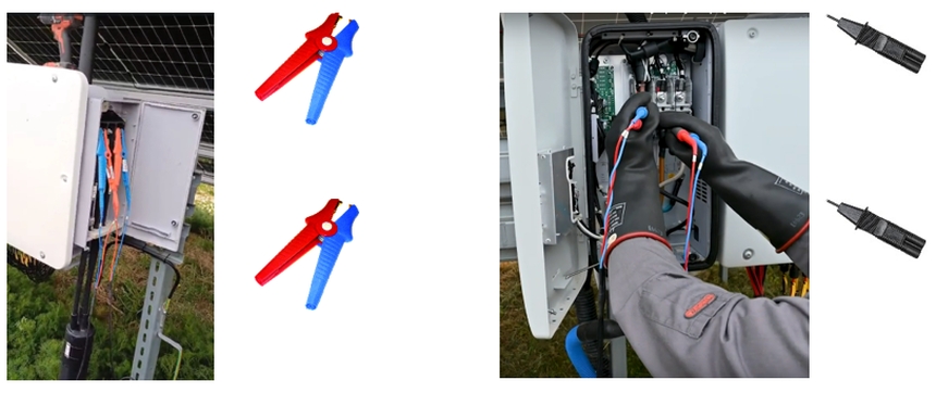
Fig. 7. Photos showing how to connect to a selected circuit using crocodile clips (left) or pointed probes (right)
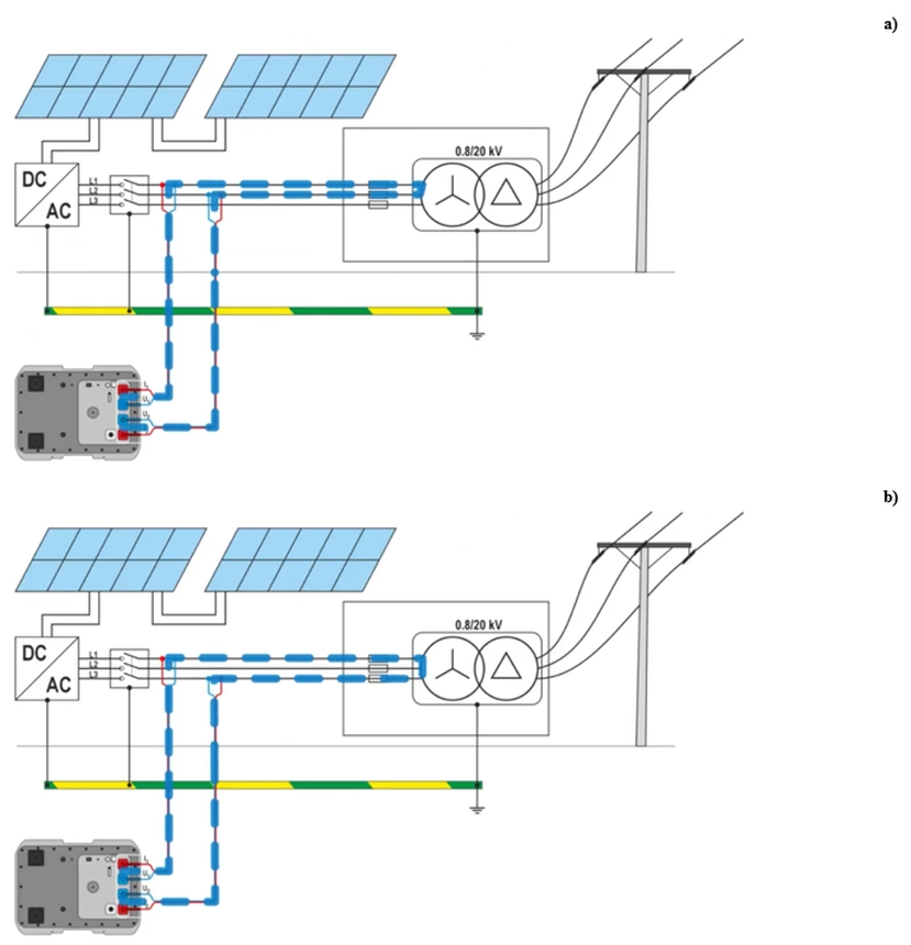
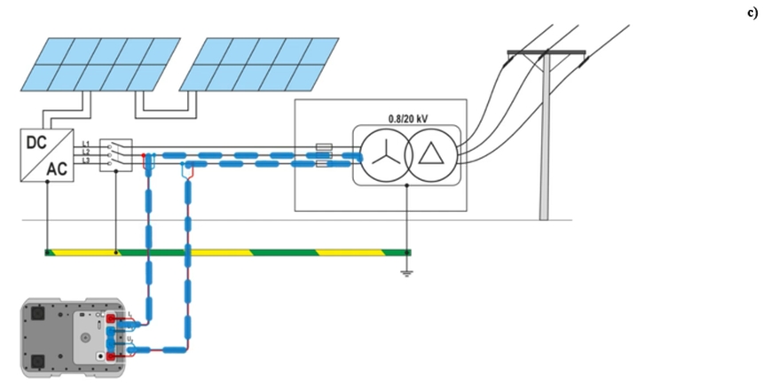
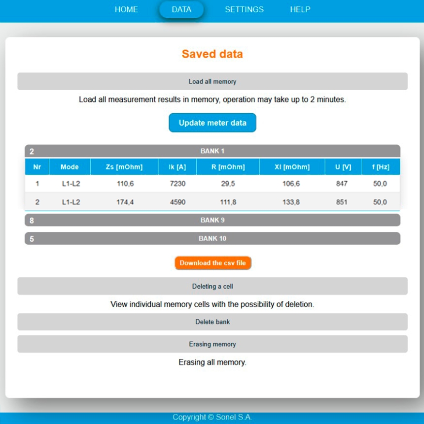
Fig. 8. Fault loop measurement for measurements in phases: a) L1-L2, b) L1-L3, c) L2-L3, d) recorded results
B. Measurements of ZS at the inverter and line fault in the transformer station (case of double fault in the circuit)
As in the case of phase-to-phase measurements, the inverter is turned off. At the other end of the tested line, at the transformer station, disconnect the incoming line from this inverter – for this purpose switch off the fuse switch connector. Alternatively, disconnect the entire station from the power supply. Using a voltage tester, make sure that there is no voltage in the tested circuit (i.e., confirm that the correct line has been disconnected). First, connect the earthing device to the earth potential (e.g., the substation’s protective earthing), and then to the phase of the disconnected line (e.g., L3). This simulates a fault in the circuit on this line.
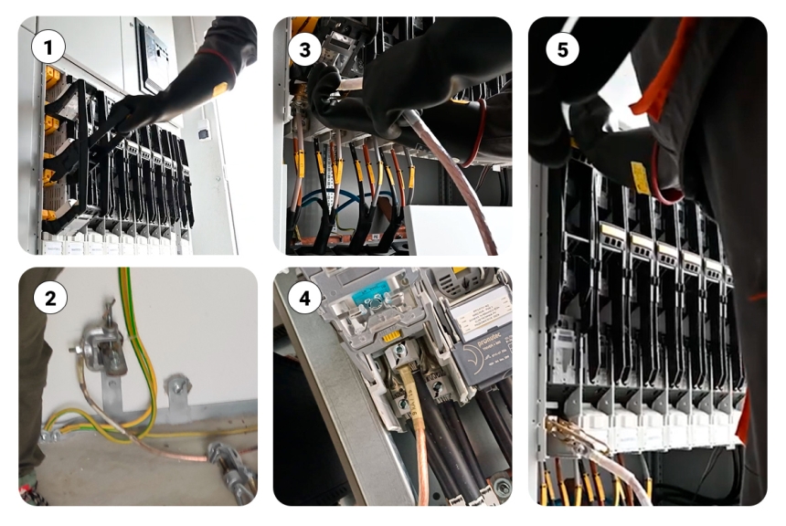
Fig. 9. Diagram of steps preparing the installation for measurement
1. Circuit disconnection using a fuse switch. 2. Connecting the earthing device to the station’s PE conductor. 3. L3 line earthing. 4. It is possible, although not recommended, to connect the earthing to the V-terminal of phase L3. 5. Reconnecting the circuit
For safety reasons, it is not recommended to connect the earthing device to the busbars of compact circuit breakers (i.e., between the transformer and the fuse switch disconnectors) or to one of the low-voltage terminals of the transformer. For the same reason, we recommend against bridging the transformer spark gap.
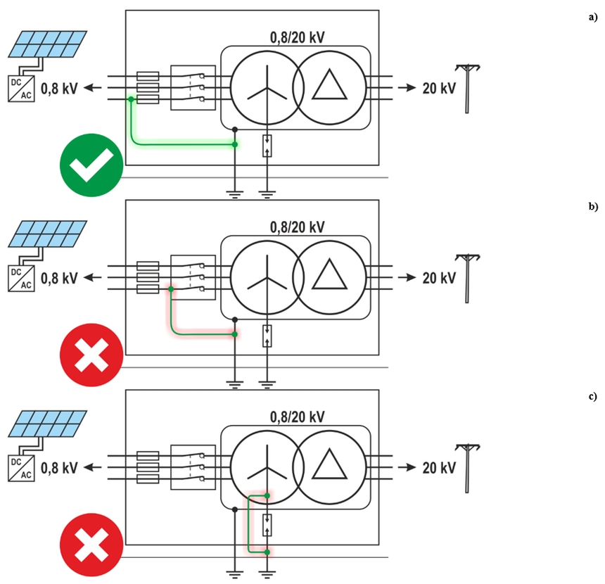
Fig. 10. Methods of simulating a fault in the circuit: a) at the output of the fuse switch disconnector (safe), b) on the busbar of the compact circuit breaker (unsafe), c) bridge on the spark gap (unsafe)
After simulating the first fault in the circuit, power can be restored by using the fuse switch disconnector that was previously switched off. Alternatively, if the substation was completely shut down, the compact circuit breaker can be switched on remotely. Do not switch the inverter on!
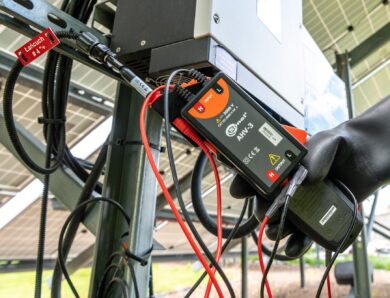
At the inverter, connect one of the test leads of the Sonel MZC-340-PV meter – the one with the crocodile clip – to the metal mounting structure of PV panels to provide direct connection to the earthing (e.g., earthing strip). Connect the second test lead to phase L1 (measured voltage: 847 V AC). In other words: in a system in which the first fault in the circuit was simulated on phase L3, establish the second fault point at the inverter terminals (the meter initiates a controlled fault), as shown in Fig. 6a. Record the result in the meter memory as L1-PE.
Without disconnecting the lead with the crocodile clip from the earthing (PE), connect the second lead from phase L1 to phase L2 and then start another measurement. Record the result in the meter memory with the annotation “L2-PE.”
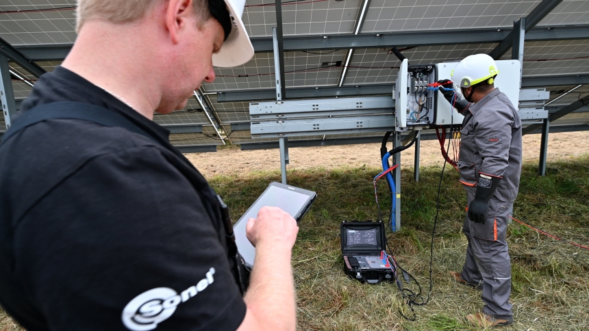
Fig. 11. Remote measurements using the Sonel MZC-340-PV meter
Perform the same connection and measurement operations for the remaining phases of a given line at the selected inverter. After turning off the power supply at the substation, reconnect the earthing wire from phase L3 to phase L2 to simulate a fault in the latter circuit. Then turn on the power supply and perform short circuit loop impedance measurements for L1-PE and L3-PE at the inverter, and record the obtained values in the meter’s memory.
Then, after turning off power supply again at the station, reconnect the earthing device to phase L1. After turning on the power supply, perform short circuit loop impedance measurements for L2-PE and L3-PE and, of course, record the results.
Once the measurements are done, the installation should be restored to its original condition. Make sure that all conductors and terminals (including V-terminals), if previously loosened, have been re-tightened using a torque compliant with the values specified in the technical documentation. Use a torque wrench for this purpose.
9. Discussion of measurement results
In order to assess the effectiveness of protection against electric shock and the selectivity of protection, we will analyse the obtained measurement results on the example of the short circuit loop impedance for the L1-PE connection with the earthed phase L3 We assume that phase-to-phase measurements (e.g., L1–L2) do not require further interpretation; however, if necessary, a detailed analysis can be prepared for any selected combination of connections.
A. Measured parameters for L1-PE
Short-circuit loop impedance: ZS=170.8 mΩ
B. Protection evaluation based on time-current characteristics
To verify the effectiveness of overcurrent protection, it is necessary to refer to the characteristics of the protection device used. The following protection device was used in this case:
Protection type: Ultra Quick NH1 M1 gS 200A 800V AC
Manufacturer: ETI Ultra Quick NH1 M1 gS 200A 800V AC (p. 121).
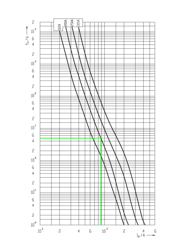
Fig. 12. Time-current characteristics of fuse links ETI Ultra Quick NH1 M1 gS 800 V AC
- Based on the design documentation of the tested installation, we conclude that in the event of a second fault in the circuit, the IT network system will become a TN system (all panel support structures with inverters are connected to the common PE collective earthing and transformer station – see Fig. 3c, Fig. 4b).
- Assuming the criteria for the tested system with a nominal voltage of 800 V AC, the required maximum disconnection time in the TN network is 5 seconds.
C. Verification of automatic disconnection condition
To ensure the effectiveness of protection against electric shock in an IT system, it is necessary to check whether the measured short circuit loop impedance ZS meets the installation 5 seconds.
D. Calculation of the maximum permissible short circuit loop impedance
According to the definition, the measured short circuit loop impedance ZS cannot exceed the limit value ZSmax, and therefore:
ZS ≤ ZSmax
ZSmax = U0/(2 žIa)
Zs≤
with:
- U0 – nominal phase voltage relative to earth. In the case of the second fault, the phase-to-phase voltage in the IT system becomes, in this example, the phase voltage of the TN network into which the analysed system has been transformed (e.g., for an IT network with a nominal phase-to-phase voltage of 800 V, this value, 800 V, should be used in the given formula).
- Ia – the current that trips the protective device within a maximum time of 5 s (877 A for the fuse used).
E. Comparison with the actual value of the short circuit loop impedance
Measured value ZS: 170.8 MΩ
Limit value ZSmax:
ZSmax = U0/(2žIa)= 800 V / (2*877 A) = 800 V / 1754 A = 456.1 mΩ
Since ZS ≤ ZSmax:
170.8 mΩ ≤ 456.1 mΩ
…therefore the condition for automatic disconnection is met.
F. Conclusion
The measured short circuit loop impedance meets the requirements for effective automatic power disconnection within the required maximum time 5 s when using the NH1 M1 gS 200 A protective device
10. Summary and recommendations for short circuit loop impedance measurements in IT networks at PV farms
Measurement of loop impedance in IT systems at photovoltaic farms with voltages exceeding 800 V requires special caution, the use of appropriate measuring equipment, and strictly defined procedures to ensure the safety of the personnel performing the measurements. Failure to follow these guidelines may result in electric shock or serious damage to the installation.
Safety recommendations and good measurement practices
- The measurements must be performed by at least two people with appropriate qualifications (SEP E+D or other licenses issued by national technical organizations in the electrical industry), training and experience in working with IT networks.
- Before starting work, analyse possible emergency scenarios and discuss the rules of conduct in hazardous situations.
- Before starting measurements, become familiar with the technical documentation of the PV farm, including electrical diagrams, earthing system layout and type of protection.
- A switching operation plan must be developed and approved in advance to avoid uncontrolled switching operations that could result in a short circuit or pose a danger to personnel (work should be carried out so as to avoid shutting down the entire farm).
- Always use certified protective equipment for working under voltage, including:
- electrically insulating gloves (adapted to the working voltage),
- safety helmet,
- electrically insulating footwear,
- flame retardant clothing,
- electrical insulating covers and mats in the working area.
- For short circuit loop impedance measurements in IT networks where the phase-to-phase voltage may exceed 800 V (e.g. in IT networks with a nominal voltage of 800 V), it is absolutely necessary to use a meter in the category CAT IV 1000 V, as during the above-described measurements, the phase-to-phase voltage of the IT network becomes a voltage relative to earth. Currently, the only device that meets this requirement is the Sonel MZC-340-PV meter. Other devices (e.g. Metrel Eurotest XC MI 3152, Chauvin Arnoux CA 6117, Sonel MZC-330S) cannot be used, because their category is CAT IV 600 V, so they can be applied for measurements in IT networks with a voltage up to 600 V.
Finally, it is also worth pointing out the difficulties related to the implementation of measurement tasks in the context of the provisions of REN (Rasjonell Elektrisk Nettvirksomhet – an organization dealing with standards and guidelines for the energy sector in Norway) and the requirements for measuring the short circuit loop impedance in IT networks, in particular in industrial facilities, power infrastructure or specialised installations such as fish farms. This issue is particularly difficult in the context of the voltage of 1000 V, which is at the boundary between low voltage (LV) and medium voltage (MV).
According to RENblad 9116, insulation monitoring is necessary (faults may remain undetected for a longer period of time – up to 4 weeks) and appropriate protection measures should be used. RENblad 4002 LS Nett also imposes requirements for providing power supply of 1000 V in IT network systems. This voltage involves additional challenges for electricians performing short circuit loop impedance measurements, especially due to the specific requirements of the standard regarding electric shock protection.
It is difficult to measure short circuit loop impedance under these conditions because specific safety requirements must be considered at a voltage of 1000 V, which is at the boundary between low and medium voltage. Too high a value of the short circuit loop impedance may cause the protection system to fail to respond on time, creating a risk of electric shock with consequences much worse than in the case of a lower voltage network. In addition, in such installations it is necessary to provide appropriate additional protection, which places additional requirements on the staff performing the measurements.
For this reason, the measurement of ZS in installations with a voltage of 1000 V requires particular precision and care to ensure full safety of users and compliance with the requirements of the standards for protection against electric shock.
Authors:
mgr inż. Wojciech Siergiej, mgr inż. Witold Dekiert, mgr inż. Robert Pawłowski
Sonel S.A.
No Comment