Sonel MRU-12 compact meter: precise earth resistance measurements
Discover the advantages of the Sonel MRU-12 – a new meter for measuring earth resistance and soil resistivity. The compact structure, durable and robust enclosure, many measurement methods and numerous functions make it perfect solution for demanding measurement conditions.
Ergonomic enclosure and easy-to-clear display
The Sonel MRU-12 enclosure is renowned for its ergonomics. The combination of plastic and rubber components prevents accidental slipping from the hand and provides protection against impacts.
With a protection level of IP65 (EN 60529:1991), the instrument’s electronics are protected from environmental conditions. The first digit indicates dust-tightness and the second one – protection against a jet of water acting on the meter from either side. The meter is designed to operate in harsh measurement conditions, which is extremely important when measuring earth resistance and soil resistivity.
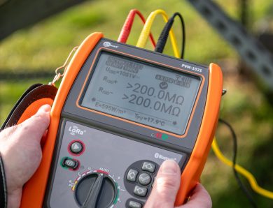
The large, easily readable, backlit display ensures that settings and results can be read in all conditions. The display presents detailed measurement data, such as:
- earth resistance and soil resistivity measurement result,
- auxiliary electrodes resistance values,
- interference voltage value,
- additional error introduced by the resistance of auxiliary electrodes.
Figure 1. Sonel MRU-12 earth resistance and soil resistivity meter
Memory and power supply
The results of earth resistance and soil resistivity measurements can be stored in the memory of the device, divided into 10 banks of 99 cells each. The collected data can be sent to a computer via Bluetooth® wireless interface to the free Sonel Reader software.
The Sonel MRU-12 meter can be powered by AA alkaline batteries (LR6) and AA rechargeable batteries (R6). The optimised power supply allows to perform over a thousand measurements without changing the battery set. Such versatility allows to change the power source even in emergency situations at the measuring site.
Measurement methods
As mentioned in the introduction, Sonel MRU-12 offers a number of functions and measurement methods. It enables, among others:
- measurement of earth resistance using the two-pole method (RE2P)
- measurement of earth resistance using the three-pole method (RE3P)
- measurement of earth resistance using the four-pole method (RE4P)
- measurement of soil resistivity using the Wenner and Schlumberger (ρ) methods
Before the measurement, the meter monitors if a dangerous interference voltage is present on the connected object. Measurement is possible up to a voltage value of 24 V. Above this value, measurements are blocked for safety reasons and the voltage influence on the results.
In order to separate from the negative impact of mains frequency interference, the Sonel MRU-12 performs measurements using a voltage and current frequency of 125 Hz for 50 Hz mains and a frequency of 150 Hz for 60 Hz mains.
It is worth mentioning that Sonel MRU-12 generates sinusoidal voltage and measurement current. Many meters on the market perform measurements with rectangular-shaped alternating current, which is typical for low-quality budget devices.
Measurement of earth resistance using the two-pole method (RE2P)
For the measurement of earth resistance in certain situations the two-pole method can be used. When the earthing system is known and an earthing with a known resistance value is available, the result of the measurement will be the sum of the resistances of earthing: the earthing measured and the one with a known value.
Figure 2. Two-pole method RE2P
Measurement of earth resistance using the three-pole method (RE3P)
During the measurement of the earth resistance with the three-pole method, the instrument measures the voltage drop on the earthing and the current flowing through it. Based on this data and on Ohm’s law, the resistance is calculated. The measurement method requires the placement of two auxiliary electrodes:
- electrode H (the so-called current electrode) to enable to force the current flow in the circuit: measured earthing RE → MRU-12 → current electrode H → earth → measured earthing,
- electrode S (the so-called voltage electrode) to measure the voltage drop across the resistance of the measured earthing as a result of the flowing current.
The electrodes are placed in one line. The voltage electrode is placed at approximately 62% of the distance between the current electrode and the earthing tested. In this method the important point is to position the auxiliary electrodes so that a zero potential spot is present. To make sure that the voltage electrode insertion point has been selected correctly, two additional measurements should be taken by moving the voltage electrode once towards the tested earthing and once towards the current electrode by several metres. If the results do not differ by more than 3%, it can be assumed that we are in the zero potential zone.:
Figure 3. Measurement of earth resistance using the three-pole method RE3P
Measurement of earth resistance using the four-pole method (RE4P)
In the case of measurements of earthing with small resistance values, in order to maintain high measurement accuracy, resistance measurements can be performed with an additional fourth wire. This eliminates the resistance of the wire connecting the meter to earthing.
Figure 4. Measurement of earth resistance using the four-pole method RE4P
Measurement of soil resistivity using the Wenner and Schlumberger (ρ) methods
Soil resistivity measurements are used in the preparation of earthing system projects, in cathodic protection or in geology and physical soil investigations.
In the Wenner method, four electrodes are placed in the ground, in a line, at equal distances. A typical feature of the Wenner method is the relationship between the distance between the electrodes and the depth through which the flowing current penetrates.
Figure 5. Soil resistivity measurement using the Wenner method
In the Schlumberger method four electrodes are also placed in a line, but the distances between them are different. Between electrodes E and ES and between S and H the same distance is maintained. At the same time, it is important to note that when measuring with the Sonel MRU-12 meter, it must be at least three times the distance between the ES and S electrodes. The measurement consists in changing the location of the current electrodes without changing the distance between the voltage electrodes.
Figure 6. Soil resistivity measurement using the Schlumberger method
Ready measurement set
According to the Sonel standard of providing customers with ready sets for basic measurements, the Sonel MRU-12 is sold with a set of accessories. The box, in addition to the meter, includes:
- measuring wires of length: 2.2 m (2 pieces), 15 m (2 pieces) and 30 m (1 piece);
- ground electrodes (4 pieces);
- crocodile clips (4 pieces);
- holder for hanging the meter;
- case and neck strap;
- set of batteries;
- factory calibration certificate.
Figure 7. Standard accessories included with Sonel MRU-12
Author:
Adam Szczepanik
Sonel S.A.
No Comment